
Industrial Camera ROI Configuration and Acquisition Performance Optimization
How to Increase Frame Rate, Reduce Bandwidth Usage,
Industrial Camera ROI Configuration and Acquisition Performance Optimization
1. Introduction: Why Does ROI Configuration Matter in Machine Vision?
In industrial automation and machine vision inspection, industrial cameras must deliver not only sufficient image resolution but also the speed, responsiveness, and stability required by production lines. Even when a camera supports high resolution and frame rates, the overall system may be limited by interface bandwidth, image-processing capacity, memory usage, or data-transfer efficiency.
This is where ROI (Region of Interest) configuration becomes an important image acquisition optimization technique.
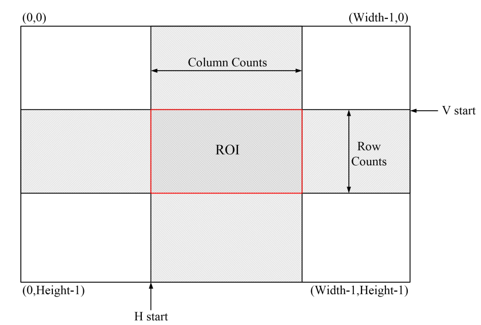
ROI allows users to define the image area that needs to be acquired or processed. For example, in electronic component inspection, if the inspection task focuses only on the pins of a connector, the system may use an appropriately sized image region instead of always operating at the sensor's full resolution.
Proper ROI configuration can reduce the amount of image data per frame, lower downstream processing requirements, and potentially increase the achievable acquisition frame rate when the camera supports the appropriate readout mode.
However, ROI is not a universal solution to every performance problem. Its actual benefits depend on how the camera sensor, driver, interface bandwidth, acquisition software, and inspection algorithms work together.
2. What Is ROI in an Industrial Camera?
ROI stands for Region of Interest. It refers to a designated area of an image used for acquisition, observation, or processing. In an industrial camera system, ROI is commonly defined by setting the starting coordinates, width, and height.
Typical ROI parameters include:
| Parameter | Description |
|---|---|
| Offset X | Defines the horizontal starting position |
| Offset Y | Defines the vertical starting position |
| Width | Sets the horizontal size of the ROI |
| Height | Sets the vertical size of the ROI |
For example, an industrial camera with a resolution of 2448 × 2048 may be configured to acquire a 1200 × 1000 pixel region, provided that the camera supports the required ROI settings. The offset coordinates determine where this region is located on the sensor.
There are two important implementation approaches:
- Sensor-level ROI: The camera reads out a smaller sensor region. This is more likely to reduce readout data and may increase frame rate.
- Software cropping: The camera captures and transfers the full image before software crops the target region. This can reduce downstream processing requirements but generally does not reduce the full-image transfer that has already occurred.
Therefore, when evaluating industrial camera ROI functionality, engineers should verify how the feature is implemented in the camera and SDK rather than simply checking whether an ROI option exists in the software.
3. How Can ROI Improve Industrial Camera Acquisition Performance?
3.1 Reduce Image Data per Frame
The most direct benefit of ROI is reducing the number of pixels in each acquired frame.
Suppose an industrial camera provides a full resolution of 3840 × 2160 pixels, while the inspection task requires only a 1920 × 1080 region.
| Parameter | Full Image | ROI Image |
|---|---|---|
| Image width | 3840 px | 1920 px |
| Image height | 2160 px | 1080 px |
| Total pixels | 8,294,400 | 2,073,600 |
| Relative pixel count | 100% | 25% |
With the same pixel format, the ROI image contains only 25% of the full image's pixels. Under ideal conditions, the raw image data per frame can therefore decrease by approximately 75%.
This can reduce pressure on image transmission, buffering, memory management, and downstream processing.
Actual data volume may also be affected by pixel packing, transmission protocols, metadata, and other overhead. As a result, the reduction in transferred bytes may not exactly match the reduction in pixel count.
3.2 Increase the Achievable Frame Rate
When sensor readout time limits an industrial camera's frame rate, reducing the ROI may decrease the amount of data read per frame and improve acquisition speed.
For some cameras with flexible ROI readout modes, reducing image height can decrease the number of rows that must be read and shorten frame readout time. The actual improvement depends on sensor architecture and camera firmware; not every model increases its frame rate in the same way.
If exposure time is the primary bottleneck, however, reducing ROI may have little effect. For example, with a 20 ms exposure, achieving a sustained acquisition rate substantially above 50 fps may remain difficult without changing other conditions, even if readout time decreases.
Before optimizing ROI, identify whether the current limitation comes from sensor readout, exposure time, data transmission, or host processing.
3.3 Reduce Bandwidth Usage and System Load
Continuous image output can become a bottleneck in machine vision systems, especially when high resolution, high frame rates, or multiple cameras are involved.
The theoretical data rate of uncompressed images can be estimated using:
Theoretical image data rate (Bytes/s) = Width × Height × Bytes per pixel × Frame rate
For example, a camera outputting 1920 × 1200 pixel, 8-bit single-channel images at 60 fps requires:
1920 × 1200 × 1 × 60 = 138,240,000 Bytes/s, or approximately 138.24 MB/s.
If the ROI is reduced to 960 × 600 while maintaining the same frame rate and pixel format, the theoretical data rate decreases to approximately 34.56 MB/s.
This estimate excludes protocol overhead and assumes one byte per pixel. For 10-bit, 12-bit, or packed pixel formats, calculations should use the actual output representation.
Reducing data rate through ROI can ease transmission pressure on USB3, GigE, and other camera interfaces while reducing demands on host buffers and storage. However, lower bandwidth does not necessarily produce a higher frame rate if another factor limits camera performance.
3.4 Reduce Image Processing Time
In practical machine vision applications, image acquisition is only one part of the workflow. Images may also require preprocessing, positioning, measurement, defect recognition, or OCR.
When the processed image area becomes smaller, the algorithm generally needs to process fewer pixels. Template matching, edge detection, thresholding, and some morphological operations may therefore require less computation.
Actual speed improvements depend on the algorithm, number of targets, CPU or GPU performance, and software implementation. More importantly, the ROI must include every region that needs inspection. Faster processing is not useful if the ROI cuts off a defect or target.
4. ROI Configuration Strategies for Different Industrial Inspection Applications
ROI should not simply be reduced to the smallest possible image size. It must match the inspection target, object motion, and positioning accuracy.
4.1 Electronic Component and Connector Inspection
In electronics manufacturing, industrial cameras can inspect connector pins, solder joints, component positions, terminal deformation, and assembly completeness.
If the inspection focuses on connector pins, the ROI can be positioned around the target area to reduce background pixels and irrelevant image data. For products with multiple variants, the ROI may be adjusted according to the product model, positioning results, or inspection recipe.
Important considerations include:
- Full coverage of pins and terminals;
- Product positioning tolerances;
- Defects that may occur near the edges;
- ROI updates when switching between product variants;
- Retaining surrounding areas needed for positioning or dimensional measurement.
ROI should be based on a reliable positioning method. If workpiece positions vary significantly, an excessively small fixed ROI may exclude pins or defects from the acquired image.
4.2 High-Speed Packaging and Label Inspection
On packaging lines, cameras may inspect label placement, printing defects, date codes, barcodes, and seal integrity. For products moving at high speed, acquisition timing, exposure time, and trigger synchronization are often more important than simply reducing image resolution.
ROI can focus acquisition on labels, date codes, or sealing areas, reducing unnecessary data transfer and algorithm processing.
However, if product positions vary on the conveyor, sufficient margin must be provided for the full target movement range. In systems triggered by encoders or photoelectric sensors, verify the relationship between trigger signals, exposure time, and ROI position to avoid missed inspections caused by target displacement.
4.3 Precision Measurement and Dimensional Inspection
In dimensional inspection, ROI can isolate the measurement object, reduce background interference, and limit the processing area for edge detection or geometric fitting.
ROI itself does not improve measurement accuracy. Final accuracy still depends on optical quality, calibration, pixel sampling, illumination, workpiece stability, and algorithm design.
If object edges may shift with product positioning, retain an appropriate margin. For high-repeatability measurement systems, use reference samples to validate measurement error and repeatability before and after ROI changes.
4.4 Multi-Camera Vision Systems
In multi-camera systems, every camera generates its own image stream. Simultaneous transmission can increase demands on host interfaces, network switches, memory, and storage.
If each camera only needs to inspect a local area, configuring separate ROIs can reduce the data volume per stream. However, multi-camera systems must also account for trigger synchronization, acquisition timing, shared bandwidth, and host processing capacity.
For GigE camera systems, check link speed, switch configuration, and the combined data rate of all streams. For USB3 systems, examine host controllers, port allocation, and actual transfer capacity. The practical limits depend on the system architecture and cannot be determined from theoretical interface bandwidth alone.
5. Common Industrial Camera ROI Problems and Solutions
5.1 Why Does Frame Rate Remain Unchanged After Reducing ROI?
Possible causes include:
- Cropping occurs only in software while the sensor still outputs the full image;
- Exposure time is the primary frame-rate limitation;
- The camera firmware or sensor readout mode does not become faster when ROI changes;
- Acquisition software, image-processing algorithms, or other devices limit the overall workflow.
Check the camera manual and SDK to confirm whether ROI affects sensor readout. Then measure acquisition frame rate, image transfer speed, and algorithm processing time separately to identify the actual bottleneck.
5.2 Why Does Image Acquisition Fail After Configuring ROI?
Some industrial cameras impose restrictions on ROI width, height, starting coordinates, or increment values. Invalid settings may cause configuration errors, unexpected image dimensions, or acquisition failures.
Recommended troubleshooting steps:
- Confirm that all ROI parameters fall within the camera's supported ranges.
- Check whether the combination of Offset X, Offset Y, Width, and Height is valid.
- Verify any alignment or increment requirements for width, height, and offsets.
- Check whether the SDK requires image dimensions to be configured before offset coordinates.
- Read the camera parameters again to verify that the settings were successfully applied.
Restrictions and configuration order vary by camera model. Always refer to the corresponding SDK documentation.
5.3 What Should You Do If ROI Configuration Causes Missed Defects?
When the ROI is too small, target edges, small defects, or positioning errors may place part of the inspection target outside the acquired region.
Recommended practices include:
- Add margins based on workpiece positioning tolerances;
- Validate coverage using both normal and defective samples;
- Test variations in product position, angle, and size;
- Create specific test cases for edge defects;
- Revalidate detection and false-positive rates after changing the ROI.
ROI optimization should maintain inspection coverage and image quality rather than simply minimizing image dimensions.
5.4 How Can Frame Loss Be Reduced During Industrial Camera Acquisition?
Frame loss is not necessarily caused by ROI or camera frame rate. It may also result from insufficient bandwidth, high host resource usage, buffer configuration, cable connections, or simultaneous acquisition from multiple cameras.
Recommended checks:
- Data rate: Calculate the theoretical data rate from resolution, pixel format, and frame rate, then compare it with available bandwidth.
- ROI: Evaluate whether sensor-level ROI can reduce data volume without compromising inspection coverage.
- Interface connections: Check USB3 ports, GigE network links, cables, and associated hardware.
- Host load: Monitor CPU usage, memory, disk-write speed, and image-processing threads.
- Acquisition buffers: Review SDK buffer counts, callback processing speed, and persistent buffer buildup.
- Sustained testing: Run long-duration acquisition near actual production speed and record the number and timing of dropped frames.
Distinguish between images that the camera fails to acquire, data lost during transmission, and frames that the application fails to process in time. These problems require different solutions.
6. ROI and Industrial Camera Selection: How Should You Choose the Right Interface?
ROI can help optimize image data volume, but it cannot replace proper camera selection. Before choosing a camera, consider target dimensions, required resolution, object speed, acquisition frame rate, transmission distance, and the number of cameras in the system.
| Interface | Typical Characteristics | Selection Considerations |
|---|---|---|
| USB3.0 | Suitable for compact systems and relatively high data throughput | Host controller, cable length, actual bandwidth |
| GigE | Suitable for systems requiring longer cable runs and network connectivity | Network links, switches, shared bandwidth |
| 10GigE | Suitable for higher-throughput networked imaging systems | Network hardware, host compatibility, storage performance |
| CoaXPress and other high-speed interfaces | Can support specialized high-bandwidth, high-speed vision systems | Frame grabber, cabling, system cost, compatibility |
The final choice should be based on the actual data throughput of the complete system and the application's requirements, rather than nominal interface speed alone.
How Can MindVision Industrial Cameras Support ROI Optimization?
MindVision offers industrial imaging products across USB3.0, GigE, 10GigE, and other interface categories for applications such as automated inspection, dimensional measurement, electronics manufacturing, and OEM vision equipment. Resolution, frame rate, shutter type, and interface options vary by model, so ROI optimization should be matched to the capabilities of the selected camera.
For example, MindVision's MV-SUS840C/M is a USB3.0 industrial camera with a listed resolution of 3840 × 2160 and a maximum frame rate of approximately 45.5 fps on its official product page. For machine vision projects requiring relatively high resolution, engineers can evaluate its performance in target-region acquisition, data transmission, and host processing. Whether ROI can increase frame rate must be confirmed through the camera's supported ROI modes and practical testing.
For inspection systems requiring network connectivity, a GigE camera can also be evaluated. The MV-GE507GC/M, for instance, offers 2448 × 2048 resolution, 5 MP, and a global shutter. For applications involving moving targets or external triggering, engineers should assess ROI, exposure time, trigger synchronization, and actual acquisition speed together.
MindVision product information and technical documentation can help verify camera specifications and integration requirements. The supported ROI range, configuration sequence, frame-rate changes, and interface throughput should be confirmed using the documentation and test results for the specific model.
7. Best Practices for Industrial Camera ROI Optimization
To make ROI optimization effective in production, use a systematic testing process.
- Define the inspection target: Identify the required target area, defect size, and inspection accuracy.
- Establish baseline measurements: Record frame rate, data rate, CPU usage, and dropped frames at full resolution.
- Reduce ROI incrementally: Adjust only the necessary parameters at each step and check image coverage and edge information.
- Measure acquisition and processing separately: Do not rely only on the FPS displayed by the application. Distinguish camera acquisition rate, transfer rate, and algorithm processing speed.
- Validate worst-case conditions: Test changes in target position, maximum production speed, different lighting conditions, and long-duration operation.
- Document final settings: Save ROI coordinates, resolution, frame rate, exposure time, pixel format, and trigger mode for reproducibility and maintenance.
A properly configured ROI should provide sufficient image coverage, meet inspection quality requirements, and maintain stable acquisition performance.
8. Frequently Asked Questions
Not necessarily. Reducing both image width and height by half reduces the pixel count to one-quarter, but a fourfold frame-rate increase depends on sensor readout mode, exposure time, camera firmware, interface, and other factors.
Camera-level ROI may reduce sensor readout and transmitted data. Software cropping typically reduces the processing area after the full image has already been transferred. Both can reduce downstream computation, but their effects on bandwidth and acquisition frame rate differ.
No. An excessively small ROI may crop targets, miss defects, or cause positioning failures. The appropriate region should reflect target size, positioning tolerances, and inspection requirements.
ROI may help when frame loss is primarily caused by excessive image data, insufficient transmission bandwidth, or host processing load. If the problem comes from trigger configuration, cable faults, buffer management, or blocked software threads, those issues must also be addressed.
If ROI changes only the readout area without changing the pixel-to-world mapping, recalibration requirements depend on the measurement workflow. However, if the image coordinate origin, field-of-view position, lens configuration, or measurement region changes, calibration parameters and measurement accuracy should be revalidated, with recalibration performed when necessary.
Check the camera manual and SDK to confirm whether ROI changes the sensor readout window. Verify the minimum, maximum, increment, and alignment rules for Width, Height, Offset X, and Offset Y. Read back the camera parameters after configuration to confirm the settings are applied. Also measure actual data rate and frame rate at full resolution and with ROI under the same exposure time and pixel format. If the transfer data rate remains essentially unchanged and only downstream processing load drops, the function is likely software cropping.
First confirm that ROI is actually applied, then identify the bottleneck: exposure time, sensor readout, interface bandwidth, host processing, or storage. Measure acquisition frame rate, transfer data rate, CPU/GPU usage, and dropped frames separately. If exposure time is longer than the frame period, optimize illumination or exposure first. If bandwidth is close to the interface limit, review pixel format, ROI, and interface configuration. If image processing or storage is the bottleneck, optimize threads, buffers, and storage strategy.
Each camera should acquire only the necessary inspection region, with synchronized triggering and acquisition timing. Calculate the combined data rate of all cameras and compare it with the actual throughput of the interface, switches, host, and storage. For GigE systems, check link speed, switch configuration, and jumbo frame settings. For USB3 systems, examine host controllers, port allocation, and actual transfer capacity. Sufficient buffers and long-duration acquisition tests under production-like conditions are also important.
ROI can reduce data volume, but it cannot replace proper exposure and trigger design. For moving targets, shorten exposure time, use a global shutter or strobe illumination when necessary, and trigger acquisition with an encoder or photoelectric sensor. Verify that trigger latency, exposure time, ROI position, and target speed are properly matched, and leave sufficient positional margin so the target does not move outside the ROI during acquisition.
Compare full-frame acquisition with ROI acquisition using the same set of samples. Record ROI coordinates, resolution, exposure time, pixel format, trigger mode, actual frame rate, transfer data rate, CPU/GPU usage, dropped frames, scan or production cycle time, detection rate, false-positive rate, image quality, and long-duration stability. ROI optimization should be considered successful only when it reduces data volume while maintaining the required inspection coverage, image quality, and repeatability.
9. Conclusion: Improve Machine Vision Acquisition Efficiency with Proper ROI Configuration
ROI is a practical technique for optimizing industrial camera acquisition performance. By appropriately reducing the region of interest, engineers can decrease image data per frame, reduce transmission and processing demands, and potentially achieve higher acquisition frame rates when the camera supports the required readout mode.
Effective optimization involves more than reducing image dimensions. Inspection coverage, exposure time, sensor readout capability, interface bandwidth, host performance, and acquisition software design must all be considered.
For electronic component inspection, packaging quality control, precision measurement, and multi-camera vision systems, identify the performance bottleneck first. Then adjust ROI through controlled testing and validate inspection quality and system stability using real samples.
MindVision offers a range of industrial camera interfaces and product solutions for machine vision projects. Engineers can evaluate suitable cameras based on inspection targets, required resolution, operating speed, transmission distance, and software environment, then verify the relationship between ROI settings and acquisition performance through practical testing.
To learn more about industrial camera products or discuss camera selection for your project, visit the official MindVision website:
Email: globalmarket@mindvision.com.cn
#MindVision
MindVision Technology Co., Ltd. is a professional domestic industrial camera manufacturer headquartered in Shenzhen, with production centers and R&D bases in Changsha (Hunan) and Wuxi (Jiangsu), employing nearly 300 people. Its product portfolio covers area-scan cameras, line-scan cameras, thermal imaging cameras, and stereo camera modules, with over 100 patents and software copyrights. The company is ISO9001 certified.
For more information or free selection consulting, please visit MindVision's official website or contact the sales team.
We’ll be glad to help you
Please Login
Full Name
Company Name
E-mail*
Country / Region
Your Needs / Application*
Verification code

Get in touch
Name*
E-mail*
Country*
Your Needs / Application*
